| Design goal |
Everyone probably knows (if one ever tried) how difficult if not impossible is getting decent signal to noise ratio from computer audio card.
I hardly managed to get -42 dB SNR on my first ESS1869 card and approx. -62 dB on Aureal Vortex.
Even latest mobo designs like Albatron board with onboard Envy24PT hardly reaches -56 dB.
High amps inside the box do their job.
If you want some better sound, the good idea is to use some external DAC or receiver capable of S/PDIF decoding.
The cheapest way is to build the DAC for an existing analog amp rather then buying the new just for S/PDIF
|
| Components and schematics
|
|
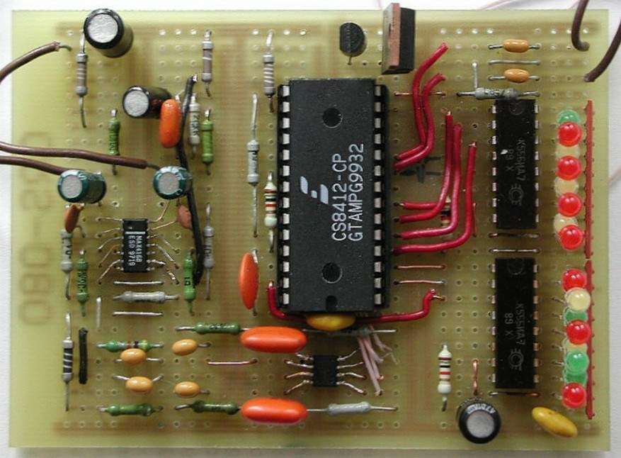
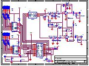
This DAC is built around 3 chips - the CS8412 S/PDIF receiver, high perfomance CS4334 delta-sigma DAC and MAX4168 opamp.
Evergreen CS8412 and CS4334 are manufactured by Crystal Semiconductors.
The most expensive part of the system, the receiver, is not easy to buy sometimes and you may expect prices around $15 per piece. The DAC itself I got as a free sample from the manufacturer. Any other with suitable interface may be used - lots of similar designs are floating around on the net. The thing is designed in 8-pin SOP case that is easy to solder.
The MAX4168 opamp is used in active 3-pole filter. The design is taken from the CS4334 evaluation board - no need to reinvent the wheel. The good thing about MAX4168 is that this rail-to-rail beast is capable to drive headphones directly - no need for dedicated headphones amp. Its output power is more than sufficient even at +5V supply voltage - "one amplifier less" (TM) design LOL.
|
| Assembling notes |
|
Take care to keep filter components for left and right channels identical and close to values specified. Use digital multimeter to select the pairs.
I used the breadboard design to save the time and effort - definitely not the best practice, so take care of the grounding wiring and power decoupling. Put enough capacitors at the digital part. In my design chip capacitors are placed straight on the power buses at the copper side of the board close to the DAC and receiver power legs. LED drivers doesnt generate much noise as there is no LED switching during the normal operation. Usually just a pair of LEDS required to display signal lock.
Resistor matix may be replaced with just a single resistor as LEDs are on only one at a time. I didnt use reference 6,14 MHz oscillator to keep radiated noise to minimum as breadboard design isnt good enough.
Two independent (7805 and 78L05) supplies were used to feed the digital and analog parts.
The active filter piece appeared being sensitive to radiated noise, so I put the whole thing into the metal screen to achieve good results. RCA jacks were used to feed power and signals inside the box.
|
| Links |
|
|